


Learn how to import 3D geometry into BUILD3D from third-party CAD software to simplify geometry creation.
This tutorial uses GeoStudio 2021.3 and will show you how to import 3D CAD files in the *.step, *.iges, *.dxf, *.dwg, and *.stl file formats.
What’s in this video?
0:00 Introduction
0:30 Three methods for importing CAD files
1:54 CAD File Types – Best Practices
3:26 Import Body in BUILD3D
5:00 Import Background Mesh in BUILD3D
6:47 Import Profiles in BUILD3D
Duration
9 min
See more on demand videos
VideosFind out more about Seequent's civil solution
Learn moreLearn more about BUILD3D
Learn moreVideo Transcript
[00:00:00.880]
<v Instructor>Welcome to the Build3D importing series.</v>
[00:00:04.500]
In this session, I will show you how
[00:00:06.229]
to import files from third party CAD sources
[00:00:10.890]
into Build3D to simplify your geometry creation.
[00:00:15.810]
This workflow is useful
[00:00:17.270]
for creating 3D analysis-ready geometry based on files
[00:00:22.470]
that have been created in CAD software,
[00:00:25.520]
removing the need to recreate the geometry in Build3D.
[00:00:31.410]
There are three methods
[00:00:32.590]
for importing CAD generated geometry into Build3D.
[00:00:37.200]
The first method is importing as 3D solids.
[00:00:41.630]
Three dimensional bodies can be imported directly
[00:00:44.410]
into Build3D if they are in the STP or IGES file format.
[00:00:52.420]
The second method is it importing as background mesh.
[00:00:56.910]
Surface meshes that have been created
[00:00:58.990]
in CAD software can be imported
[00:01:01.300]
as a background mesh in Build3D.
[00:01:04.570]
A background mesh can then be used for 3D sketching
[00:01:08.310]
or for the creation of a nerve surface, such as topography.
[00:01:13.330]
File format supported in this import type
[00:01:16.500]
include DWG, DXF or STL format.
[00:01:22.630]
The last option that I will cover today is importing
[00:01:26.070]
as a 2D or 3D sketch profile.
[00:01:30.360]
This third option for CAD importing is
[00:01:32.710]
through 2D or 3D sketch profiles,
[00:01:35.690]
which are useful or for importing design structures,
[00:01:39.250]
such as embankment cross-sections or tailings dam designs
[00:01:43.490]
into the three dimensional geometry.
[00:01:45.950]
File format supported in this import type
[00:01:48.795]
include STP and IGES format.
[00:01:53.990]
First, let’s talk about the different format types
[00:01:57.220]
that can be exported from CAD software.
[00:02:00.300]
When importing in the STP or IGES format as a solid,
[00:02:05.490]
it is best to ensure
[00:02:06.770]
that the body is a parametric representation.
[00:02:10.120]
For example, consider these three cylinders.
[00:02:13.690]
All three cylinders can be saved to the STP file format.
[00:02:17.410]
However, each have been created in a different way
[00:02:20.000]
and will behave differently when imported into Build3D.
[00:02:24.190]
The red cylinder is a parametric representation.
[00:02:27.750]
It is an extrusion surface consisting
[00:02:29.990]
of three parametric surfaces,
[00:02:33.000]
the bottom, the top and the curve side.
[00:02:36.020]
This is the prefer representation
[00:02:37.780]
of geometry in Build3D.
[00:02:40.680]
The green cylinder is a mesh representation of the surface,
[00:02:44.510]
it contains 50 vertices and 32 faces.
[00:02:48.790]
Build3D cannot import the cylinder as a solid,
[00:02:51.300]
but we will review it during the background mesh portion
[00:02:53.960]
of this video.
[00:02:57.270]
The blue cylinder is a polysurface.
[00:02:59.700]
A polysurface is a faceted nerves structure.
[00:03:03.260]
Build3D will read this representation
[00:03:06.010]
with each mesh face bred as a separate surface.
[00:03:09.870]
With this format,
[00:03:10.730]
you are able to use the geometric operations,
[00:03:13.370]
but it is not a preferred representation.
[00:03:17.070]
Let’s switch to Build3D so that we can import this file
[00:03:20.240]
with three cylinders to further illustrate
[00:03:22.520]
how these different representations are imported.
[00:03:26.430]
In Build3D, we will go to Import Body
[00:03:30.070]
and choose the cylinders.stp file.
[00:03:34.760]
This geometry was created in a third party CAD software
[00:03:38.640]
where the Z coordinate is the elevation parameter.
[00:03:42.290]
Build3D requires as Y coordinate as the elevation,
[00:03:45.760]
so we will first remap the axes using the dropdowns
[00:03:49.570]
before clicking on okay to finish importing the file.
[00:03:54.540]
Here, you can see
[00:03:55.570]
that the parametric representation imported the best
[00:03:58.710]
as it was imported as a single solid
[00:04:00.830]
with three simple faces.
[00:04:03.550]
The mesh representation could not be imported as a body,
[00:04:06.710]
so it doesn’t not show up in the geometry tree.
[00:04:10.350]
Finally,
[00:04:11.200]
although the polysurface cylinder imported as a body,
[00:04:14.360]
there are now multiple faces for the same solid
[00:04:16.830]
in the geometry tree.
[00:04:19.040]
This leads to difficulty
[00:04:20.250]
with defining boundary condition assignments
[00:04:22.410]
and generating a clean mesh without first spending time
[00:04:25.550]
to clean up the solid.
[00:04:28.010]
Now, let’s look at a file
[00:04:29.470]
that was created using the parametric representation.
[00:04:33.130]
We will delete this import step in the design history tree
[00:04:36.970]
and go back to Import Body.
[00:04:40.050]
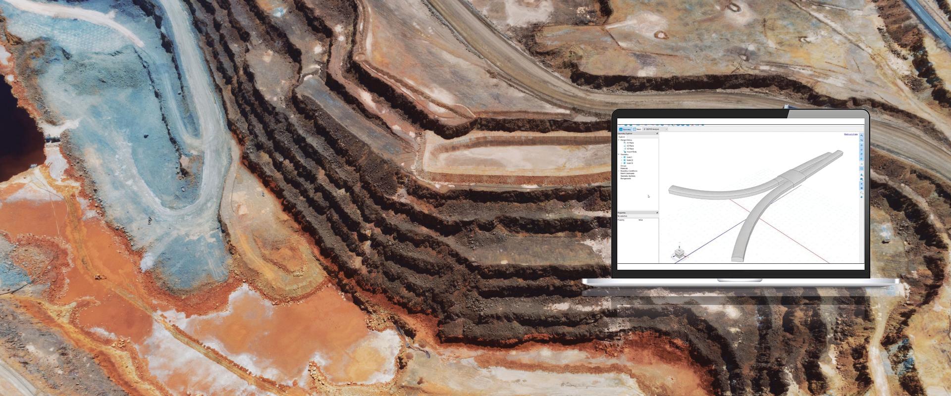
This time, I will choose the subway.stp file.
[00:04:50.610]
Once the file is remapped to the Y coordinate as elevation,
[00:04:54.390]
you can see that three solids have been imported
[00:04:56.720]
in the tunnel design.
[00:05:01.250]
Now let’s delete that import again.
[00:05:04.090]
Let’s go back to the cylinder file.
[00:05:05.930]
Except this time, we will import it as a background mesh.
[00:05:21.720]
You will see that this time,
[00:05:22.990]
only the green cylinder has been imported
[00:05:25.960]
as it was the only solid recognized as a mesh.
[00:05:29.790]
If the mesh is a structure,
[00:05:31.380]
it can be used with the sketch 2D or sketch 3D commands
[00:05:34.690]
as a snapping object while drawing.
[00:05:57.566]
If the imported file is an open surface,
[00:05:59.730]
such as a topography,
[00:06:01.650]
it is best to import the mesh surface as a background mesh
[00:06:05.470]
in either the STL, DWG or DXF file format.
[00:06:12.620]
Let’s open the ground surface DWG file as an example,
[00:06:17.070]
we will need to remap the axes like we have done previously.
[00:06:31.860]
Now, we can right-click on the mesh
[00:06:34.250]
under the background’s tree and choose Fit to Surface.
[00:06:38.730]
This opens the fit to surface window,
[00:06:41.210]
which will be discussed in the next tutorial video
[00:06:43.890]
of this series.
[00:06:48.520]
The last import feature we will discuss
[00:06:50.560]
in this video is the import profile.
[00:06:54.270]
Let’s switch to a new Build3D project,
[00:06:56.950]
which already has a geological model imported via Central.
[00:07:01.690]
For more information on importing from Central,
[00:07:04.820]
please refer to the previous video of this importing series.
[00:07:09.580]
Now, let’s say we wanted to add a tailings dam design
[00:07:13.600]
that was created in a third party software
[00:07:16.820]
to review the potential poor water pressure conditions
[00:07:19.620]
of the underlying foundation following construction.
[00:07:23.490]
To add this design to our 3D model,
[00:07:26.270]
we will go to Import Profile.
[00:07:29.560]
Here, we will choose the 2D cross-section design
[00:07:32.600]
that was created in a CAD software.
[00:07:36.120]
Once imported, we will need to ensure
[00:07:38.490]
that we remap the axes and insertion point
[00:07:41.470]
to our desired location.
[00:07:52.500]
Once the cross-section is inserted to our desired location,
[00:07:55.780]
we can now convert this profile to a solid
[00:07:58.560]
by extruding it across the geological model.
[00:08:14.502]
If we assume that nothing was removed
[00:08:16.240]
from the original topography
[00:08:17.540]
for the construction of the tailings dam,
[00:08:20.100]
we can cut the solids using the foundation materials.
[00:08:24.750]
We have now reached the end of the session.
[00:08:27.010]
Next time, we will discuss the fit to surface feature
[00:08:29.740]
in Build3D.
[00:08:31.310]
Thank you.