


Building Information Modelling/Management (BIM) is defined as ‘Use of a shared digital representation of a built asset to facilitate design, construction and operation processes to form a reliable basis for decisions. (ISO 19650:2019 referenced in Wiki). The essential elements of BIM for this discussion are the ‘digital representation’ of a ‘built asset’.
This concept has been extended most recently to include Geotechnical BIM. From Seequent’s vantage point, the ‘built asset’ might include dams, tunnels, deep excavations, waste rock piles, open pit mines and any other geo-structure. The ‘digital representation’ includes the data used to inform decisions on modeling, design, and management of the structure. This brief article discusses the following: 1) the key components of Geotechnical BIM; 2) the 3D geological model as the foundational element of the digital twin; and, 3) the challenge/opportunity geotechnical engineers face to manage geotechnical structures built in real-time by reconciling evolving site conditions and field observations/monitoring through geotechnical analyses rooted within the 3D geologic context.
Geotechnical BIM
There are effectively three key components of a Geotechnical BIM system: 1) a single source of truth; 2) change management; and, 3) the digital twin. For a single source of truth to exist, all data for a project must exist in a centralized and accessible location, allowing data as well as metadata to be constantly updated for seamless sharing by multiple stakeholders. ‘Data’ in this context has an extremely broad meaning, covering everything from site characterization and reporting to monitoring all within evolving site conditions. Change management is about version tracking the data through time.
At the core of BIM lies the digital twin. A digital twin is a digital representation of the physical system. In addition to the initial geologic model created for the site, the digital twin must also capture the evolving site conditions. A classic example would be the creation of ‘as-built’ drawings for the construction of an earthen dam or tailings storage facility. The digital twin is often associated with 3D models of civil infrastructure created in CAD programs. Design data can be combined with geotechnical data to create a 3D ground model displaying both subsurface and above ground structures. The digital twin is also a dynamic model – continuously updated as new data is made available.
3D Geological Model
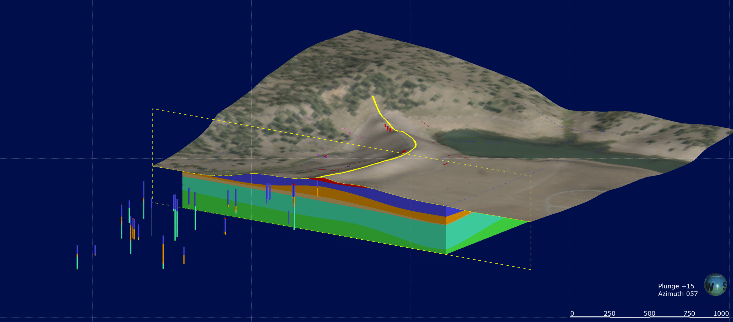
Seequent’s geological modelling and visualization application, Leapfrog, is designed to provide the core elements of a digital twin for geotechnical engineers. A Leapfrog model is constructed from a wide variety of data sources including borehole, structural, GIS, geophysical, historical cross sections, geotechnical investigation data, and more. Engineering designs from a CAD package can be incorporated directly into the geological model for rapid visualization of infrastructure such as earthworks, bridges, dams and tunnels and excavations. For a geotechnical engineer, a Leapfrog model could more aptly be called a subsurface digital twin because it can be used to model anything below the ground surface, including the geotechnical structure.
Geological models are often conceptually understood to be relatively ‘static’, created initially from observations collected during an initial characterization of the site. However, in the case of geotechnical applications the geological model needs to incorporate evolving site conditions. For example, Leapfrog is built on a technology known as fast radial-based functions. Not only does this technology provide accurate meshed surfaces for the construction of three-dimensional geological models, but it lends itself to dynamic updating. The three-dimensional geological model can be rapidly updated as new data is made available.
In addition, geotechnical engineers often employ the observational method in design and construction to avoid highly conservative assumptions about ground conditions. The observational method requires continual updates to the geological model based on observed conditions and then modification of the geotechnical design as needed to ensure the final performance targets for the structure are achieved.
Geotechnical Challenges/Opportunities
The development and updating of the geologic model (digital twin) poses some major challenges for the geotechnical engineer, but also some useful opportunities. As the geotechnical structure evolves and new observational information becomes available, the geotechnical engineer faces the challenge of updating geotechnical analyses and interpretations in response to changing site conditions including: interpretation of new observational data/monitoring data to characterize the geotechnical processes controlling performance, and, adapting the design of a structure when warranted by changed site conditions. GeoStudio is often used to help with both interpretation and design. These geotechnical analyses are often two-dimensional and must be placed within the appropriate 3D context.
Central to this approach is a dynamically updated geological model (digital twin) of the subsurface. Consider for example a weak clay seam discovered beneath a tailings storage dam during a drilling campaign or new rock bedding exposed during excavation of an open pit mine. In both cases, it is imperative that these material site changes are reflected in the geotechnical analysis. A conventional workflow in which data moves from field records to CAD drawings and eventually to the engineer does not adhere to the observational method. In contrast, a digital twin that is dynamically updated with field data and readily available to the geotechnical engineer is in-keeping with a coherent and planned strategy to manage the project.
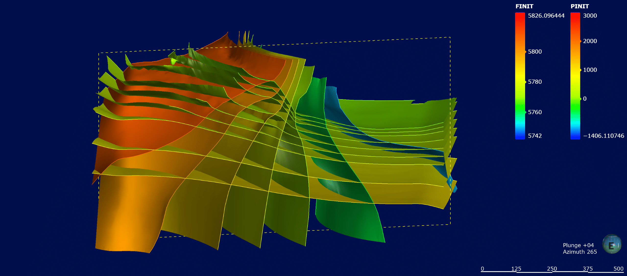
Sensors are used throughout geotechnical engineering to monitor pore-water pressures, temperatures, displacements, vibrations, climate and much more. Interpreting this data is made difficult without context. A 3D geological model (digital twin) provides the opportunity to visualize the location of monitoring instruments and/or create interpolant numeric models of the data all within the context of the geology and geotechnical structure. Coupled with the geotechnical analysis of groundwater flow, or stress-strain analysis, or any other physical process, the geotechnical engineer gains a much better understanding of the built environment by interpreting the field data in context.
Pore-pressure monitoring is one of the most common examples of this challenge and opportunity. Consider a transient pore-water pressure measurement in a highly over-consolidated sand aquifer during de-watering. A finite element analysis of the groundwater flow system can be used to understand the anticipated response because it forces the engineer to conceptualize the system, understand the geology, parameterize the materials, and apply boundary conditions. The monitoring data can then be intelligently interpreted spatially and temporarily in the context of the 3D geological model and geotechnical analysis.
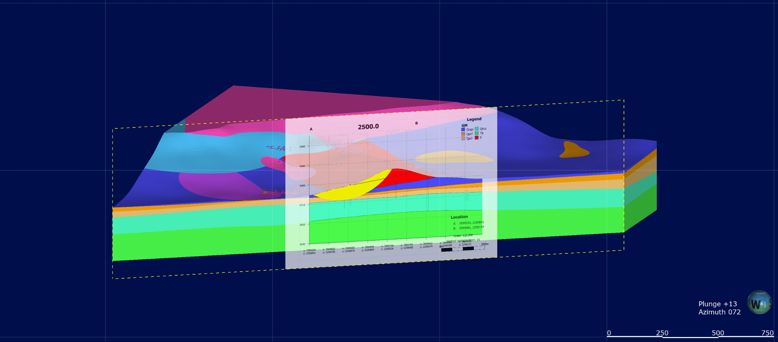
Geotechnical analysis is done mostly in two-dimensional space. In linear infrastructure projects, geotechnical analysis is conducted on a series of cross-sections spaced along the center-line of the structure. In the case of tailings dams or other large earthen dams, control sections (2D) are often used to analyze the performance of the structure through time. The necessity for 2D analysis will persist long into the future, partly because best practice demands a simple-to-complex workflow, partly because many classes of problem do not exhibit 3D behavior, and partly because 3D analysis can be time-consuming and costly.
As such, geotechnical engineers will have to reconcile a 2D-centric analysis workflow with a 3D digital twin. This reconciliation can be achieved by seamless interoperability and dynamic updating of the 2D geotechnical analysis with the 3D geological model. The two-dimensional geotechnical analysis maintains a role in geotechnical BIM provided that a dynamic link to the three-dimensional geological model is available. A static cross-section that must be manually updated does not adhere to this dynamic workflow.
Finally, the last challenge confronting geotechnical engineers is the ability to quickly update geotechnical analyses in response to changing site conditions. Consider for example the management of a fully-instrumented hydropower dam subject to a dynamic event. The dynamic event could trigger a rise in pore-water pressure which is recorded in real time via the instrumentation. This data is managed via a single source of truth and is therefore readily available to update the piezometric surfaces in the Leapfrog geological model. It is then imperative that this data flows into the geotechnical analysis such that the engineer can make informed decisions based on real-time data. This could occur by updating the piezometric surfaces in the digital twin, evaluating these piezometric surfaces on the cross-sections, and making all of this data available to update the GeoStudio analysis in near ‘real time’.
In summary, a digital twin is the sum of many parts for a geotechnical engineer. At the heart of the system lies a 3D geological model that captures the evolving site conditions and provides a transparent archive of the data sources that have been drawn upon to create this digital twin. In a geotechnical BIM, it also enables rapid re-interpretation of site conditions and evaluation of design alternatives by enabling the geotechnical engineer to rapidly and easily create numerical models drawn from this ‘single source of truth’. All these digital representations of the physical system, or digital twins, improve the engineer’s understanding of the mechanisms that control performance of the structure, thereby informing decisions around field and laboratory testing, instrumentation, design, and construction.
Find out more about Leapfrog