Introduction
This is the second of four examples demonstrating the basics of setting up three-dimensional geometries in BUILD3D. This example is a continuation of the first example from this series and demonstrates how to build two intersecting solids and use implicit and explicit Boolean operations such as cut or intersect.
Implicit Boolean Operations
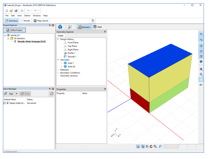
We will begin in GeoStudio with the model we created in the ‘3D Model Building Basics’ example. The selected Steady-State Seepage analysis is displayed in the Preview window. This window is a static view of the 3D domain. The Preview window does not provide any editing capabilities but we can zoom, pan, rotate, and select geometry items to preview their properties. Thus, if we modify the boundary conditions or materials colours, the Preview window will not update until we launch the 3D editor and then close it.
To edit the model, open the 3D editor by going to Define – Launch BUILD3D. We will change our extruded solids to contain a single slice. To do so, right click on Extrude 1 under Design History and select Edit from the dropdown list. In the Slices list, select slice 3, press the Delete key on your keyboard, and click OK to accept your changes. This removes the top solid from the modelled domain.
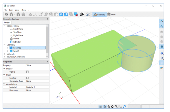
We will now add a second overlapping solid to our domain. Right click on Profile 1 under Design History and select Edit. Press the Circle sketch tool and draw a circle centred at the coordinate x=2, y=4 with a radius of 1. Press OK to accept these changes. The geometry now is an intersecting block and cylinder. You will notice the message ‘Mesh Out of Date’ on the lower right corner of the 3D view. This indicates that you changed the geometry and the current mesh no longer matches this new geometry. We will regenerate our mesh in a later step.
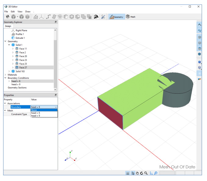
BUILD3D attempts to preserve material and boundary condition assignments when geometry changes. Thus, the block still has both a material and boundary condition assigned to it. We will remove the boundary condition from our solid. First, click on the expand arrow beside Solid 1 to see the list of faces. In the Geometry Explorer, expand the Boundary Conditions label to see a list of available boundary conditions. Boundary conditions that assigned to the domain have an arrow beside them. Select ‘head=6m’ in the Boundary list. The associated face is highlighted in the 3D view as well as in the Geometry Explorer window. Select ‘None’ in the Boundary dropdown list to unassign this boundary condition. Do the same for the ‘head=9m’ boundary condition if it is still assigned in your model.
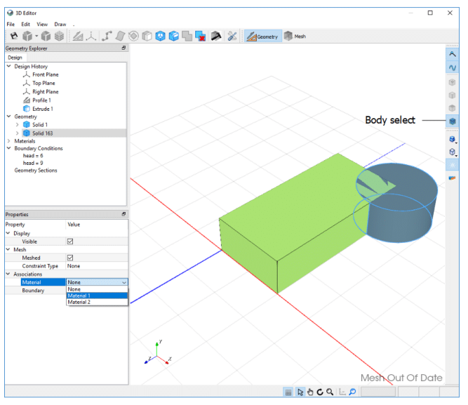
There are two materials defined in the model. Material 2 is currently assigned to the block solid, but no material is assigned to the cylinder solid. Ensure the Body select icon along the right side of the window is active, select the cylinder, and assign Material 1 to it.
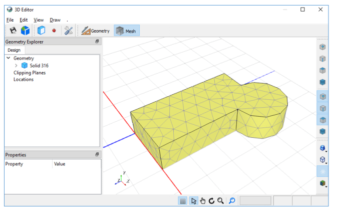
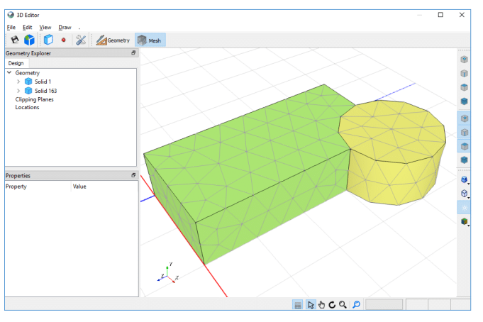
Click on the Generate Mesh icon to regenerate your model mesh and automatically change to Mesh View. You will notice that the cylinder has cut out a portion of the block solid. BUILD3D has a sophisticated set of rules that govern how materials, boundary conditions, and mesh are generated. If we do not specify any Boolean cutting or intersection operations explicitly, then BUILD3D will clean up the geometry by following implicit Boolean rules.
In this case, the cylinder solid is last in the Geometry list. Later solids trump those earlier in the list.
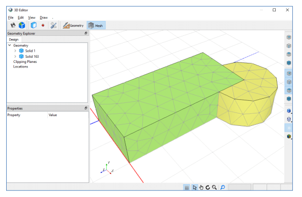
Switch back to Geometry View and drag the second solid representing the cylinder above the first one representing the block, to reverse their order in the Geometry list. Now, when the top solid in the list is selected, the cylinder should be highlighted in the 3D View.
When the mesh is regenerated the block governs over the cylinder.
Implicit cutting is extremely powerful and so we must be aware that that it is always active in BUILD3D. This could cause an issue when modifying your geometry after a model is set up. For example, if you nudge a point in Profile 1, alter the slices, or add another sketch to the profile, the solids are regenerated and any previous ordering is lost. BUILD3D tries to keep materials and boundary conditions intact, but it may not have enough information to do this correctly if the geometry changes are drastic. However, assigning materials and boundary conditions is very simple in 3D as exhibited in the ‘3D Model Building Basics’ example.
Explicit Boolean Operations: Cut
Instead of relying on the implicit Boolean operations, we can use the Cut icon to explicitly cut solids.
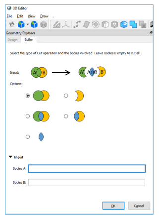
The following property sheet opens after selecting the Cut icon. It provides a choice of five Boolean operations with two sets of inputs. These two bodies, A and B, are overlapping. The selected option represents B minus A, keep A. The intersection operation can be performed on many bodies simultaneously. This means you can have multiple bodies represented by A and multiple bodies represented by B. It is easy to understand the operation with two bodies but can become confusing if too many bodies are selected. However, it is always possible to do Boolean operations one at a time if you find you are not getting the desired results with multiple selections.
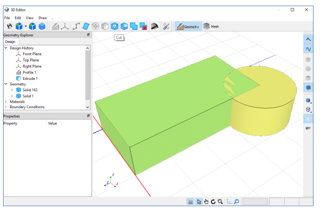
With the default cutting option still selected, click in the Bodies A box and then select the block in the 3D View. Then click in the Bodies B box and select the cylinder in the 3D View. Press OK. This operation causes the block to cut a piece out of the cylinder. Regenerate the mesh and then reorder the solids in the Geometry list. The implicit cutting has no effect when reordering the solids because the bodies no longer intersect.
Expand the bodies in the Geometry list to view their faces. You will notice that the cylinder body now has additional faces where the block cut a corner from it.
We can experiment with the various cutting options by right-clicking on Cut 1 in the Design History list and selecting Edit.
We can also experiment with modifying the Profile 1 sketch. Right-click on Profile 1 and select Edit. You will see that the changes propagate through to other features you added. Now change the number of slices, and regenerate the mesh to see what your final model looks like.
You can also delete your cutting feature by right-clicking on Cut 1 in the Design History and selecting Delete. After deleting Cut 1, your model will revert to the geometry we created with the implicit cutting operations.
Explicit Booleans: Merge
We will now use the Merge tool to combine geometry. If your model contains a single solid as a result of the Cut operations, Edit the cut feature and select a Boolean option that results in two or more solids. Or as shown here, delete Cut 1 so you end up with two intersecting solids.
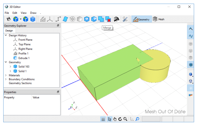
Press the Merge icon, select the geometry that you wish to combine, and click OK. Merging solids decreases the number of solids in the Geometry list. Similarly, the faces where the bodies previously intersected have disappeared and consequently the mesh quality is better. The merged body can only contain a single material so BUILD3D assigns a material based on your selections.
Merge is useful for eliminating small features in your model that do not contribute to the simulated results. For example, if we had a small thin body resulting from setting up the model geometry, we could merge it with an adjacent larger body like the soil layer above or below. The results would likely not change substantially but the mesh would be much improved because of the removal of a thin body with tiny finite elements.
Finally, we will save our model as ‘Implicit and Explicit Boolean Logic.gsz’.