


One of the major costs of an exploration project is the drilling program. Planning drillholes in 3D based on existing knowledge is an easy way to maximise the value of any future drilling, and can be achieved quickly and easily in Leapfrog Geo. This blog post will take you through the steps required to plan a drilling campaign in Leapfrog Geo, then set up a scene file so the field team can see where each drillhole should be going, as well as what lithology and grade it is expected to intercept, in 3D.
- The first step is to define your project area – a good start is to import any existing data. This could include a topography surface, any existing drillholes, an aerial photograph or geological map, and GIS data such as lakes, rivers, access roads and tenement boundaries.
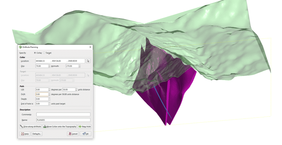
- Once you have imported the existing data, you’ll be able to start visualising in 3D where an appropriate location is to place your collar. If you’ve created any geological or grade models, you can also visualise where your potential target is.
- To create a planned drillhole, right click on the ‘Planned Drillholes’ folder, and click ‘Plan Drillhole’.
- There are two options you can choose; you can either specify a collar location or a target location. We’ll specify a collar location as it is more common to have a known point on the topography to place your collar.
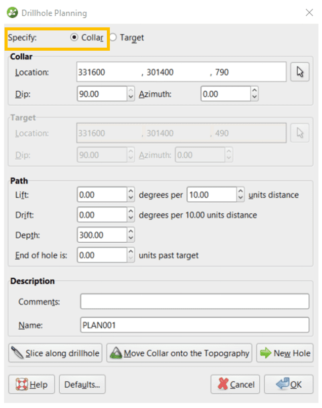
- Make sure the ‘Collar’ option is selected at the top of the window. Drag your topography into the scene, as well as an existing geological or grade model if you have one.
- Rotate the scene so you can see the collar location, as well as the point you would like to intersect.
- Click the cursor icon in the Drillhole Planning window.
- Click on the location on your topography which you would like to place your collar, and drag the cursor to your target location.
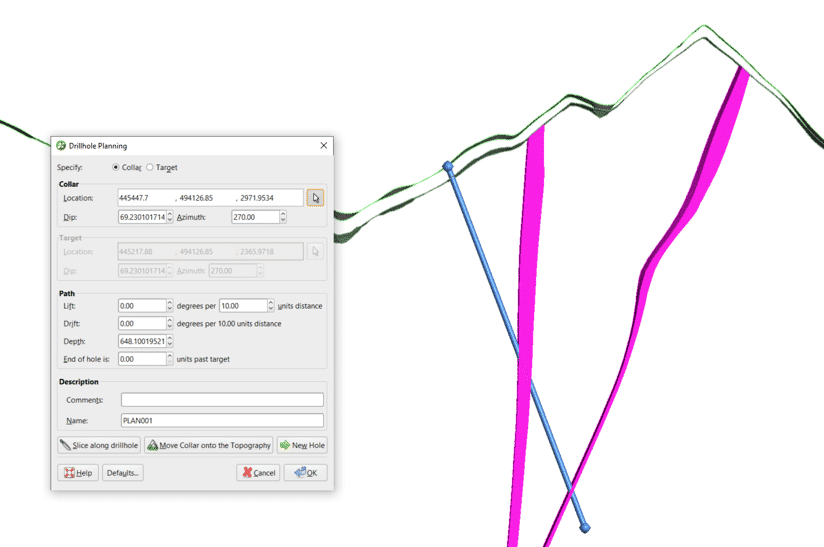
- The location, dip, azimuth and depth as well as a name for the drillhole based on the current drilling will populate the fields in the Drillhole Planning window.
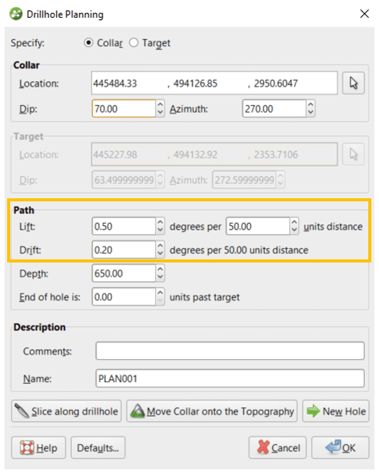
- The last step is to specify an appropriate lift and drift for your drillhole – these can be entered manually based on the trend of previous drillholes. When you change the lift and drift, you will see that your target location changes. You can manually change the dip and azimuth at surface to make sure your drillhole intercepts the desired location.
- Click OK
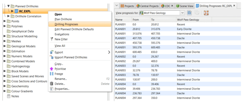
- Once you have planned your drillhole, right click on it in the project tree and select ‘Drilling Prognosis’ to view the expected lithology or grade downhole based on the current Leapfrog model.
- You can set the default lift and drift by right clicking on the Planned Drillholes folder and selecting “Edit Plan Drillholes Defaults”. In the window that appears, you can specify the default values for the lift and drift, as well as a number of other options.
- One of the more useful defaults is the “Offset to Next Hole” option, which lets you set the default distance and azimuth to the next hole. This can be very useful for planning a fence or grid of drillholes. In the example below, the default distance to next hole has been set to 50 m, and the direction between holes as well as the dip and azimuth of each hole has also been set. Once these default settings have been created, click the “Next Hole” button to create the next planned drillhole, then repeat until the desired holes have been planned.
Exporting a locations dip and azimuth
- Once your drillholes have been planned in 3D, they can be exported to a csv file to be used in the field. The exported information includes all details of the planned drillhole as shown in the image below.
Exporting to the Viewer
- Planned drillholes can also be exported in scene files along with surface data and any current models, which can then be opened in the Leapfrog Viewer available free from our website. This allows the same 3D scene to be viewed by someone without a Leapfrog licence, and is a great way for field teams to gain a better understanding of the project area.