


By H. Castellvi, X. Torelló & A. Denia
The methodology allows for a simplified simulation of the joints by assigning orthotropic properties to a plate element. It was successfully applied in the HS2 Lot S1S2 for the design of the special segments around the connections. The monitoring data and the on-site observations confirmed the accuracy of the calculations and the robustness of the design.
Tunnel structures are inherently jointed, particularly in the case of segmental linings, where the joints critically influence longitudinal behaviour and stress distribution. Traditional finite element models often neglect these joints, assuming continuous structural responses. However, this simplification could be on the unsafe side in complex scenarios like cross passages or underpasses where joint response governs load redistribution and structural performance. Additionally, the displacements in such situations tend to accumulate as differential displacements between segments, which should be evaluated during design to avoid waterproofing malfunction and structural damage.
To address these challenges, an innovative methodology was adopted that accurately simulates transversal joints within geotechnical finite element models using Seequent’s PLAXIS 3D software.
The Reduced Shell Properties Approach (Castellvi et al., 2023): Transversal joints are simulated with plate elements characterized by reduced flexural, radial shear, and torsional stiffness Longitudinal joints for simplicity of the model and robustness have been accounted using Muir-Wood equivalent inertia. These orthotropic properties are tuned through reduction coefficients RM, RQ, and RT.
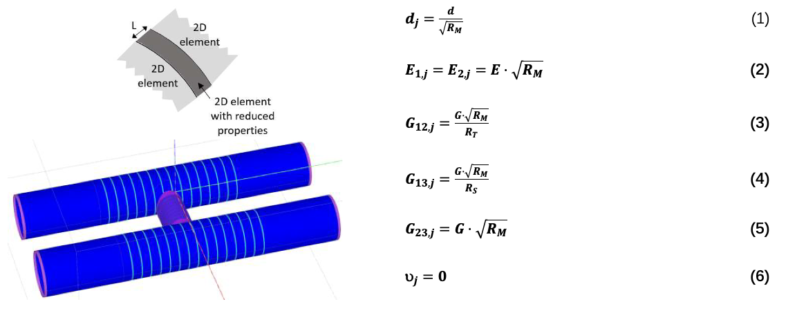
Figure 1: Geometry of the plates that simulate the transversal joints and formulation to derive the orthotropic parameters of these plates. Source: Castellvi et al. 2023.
Where the subscript j refers to “joint”, d is the segments thickness and E and G are the concrete elastic modulus and shear stiffness. Thus, considering the above modified parameters, the normal stiffnesses (E1d and E2d) and the circumferential shear (G23d) remain the same, flexural stiffnesses (E1d3/12 and E2d3/12) are reduced by a factor RM, radial (G13d) and torsional shear stiffness (G12d) at the joint is reduced by factors RS and RT respectively. Finally, torsional moment stiffness (G12d3/12) is coupled to other variables and is reduced by a factor of RM·RT. The above formulation is taken from Castellvi et al., 2023.
This method preserves linear elasticity and geometric simplicity while enabling realistic stepping and rotational behaviour across transversal joints.
Case study: Application of the methodology for the special segments design in High Speed Two project
The High Speed 2 (HS2) is a new railway currently under construction between London and Birmingham. The S1 and S2 lots include 22 km of twin tunnels below London.
In this project, the typical temporary structures around the openings and the large cross passage collars were replaced by the innovative special segments, Torelló et al. 2020. This improved the logistics inside the tunnel and reduced carbon emissions by reducing the cross passages permanent structures. These reinforced concrete elements featured embedded steel frames, prestressing rods, and shear dowels, capable of resisting high hoop stresses without temporary internal supports. This solution not only enhanced construction logistics but also won recognition at the NCE Tunnelling Awards.
Such innovative segments required an accurate design, which included 3D soil-structure finite element models at the openings.
The methodology followed by TYPSA is summarized below:
- 1) The Reduced Shell Properties Approach is used to simulate two extreme behaviours with PLAXIS 3D:
- – Rigid Pipe Model: where the thin plate simulating the transversal joint is characterized with the above formulation, considering RM=RQ=RT=1 (i.e. continuous tunnel, no joint effects).
- – Jointed Pipe Model: where RM=RQ=RT=10,000 (fully flexible transversal joints allowing independent ring movement). If relevant tension is observed in a joint, the area taking tension should be manually disconnected and the model re-run.
- 2) These models define upper and lower bounds for internal forces and displacements.
- 3) A structural model using software like SAP2000© with non-linear connectors and staged analysis is calibrated within these boundaries to ensure realistic behaviour of the special segments. This process enables an accurate calibration of the structural model. In the structural model, a more detailed representation of the specific shape of the segments may be developed if required, at the discretion of the designer.
- 4) ULS and SLS verification of the structural elements. It is remarked that limiting the stepping between adjacent segments to the gasket maximum distortion can be one of the most demanding conditions.
Note that an upper and lower boundary methodology was used for this design, but intermediate values for each of the factors may be chosen if tests are available, or in back analysis models.
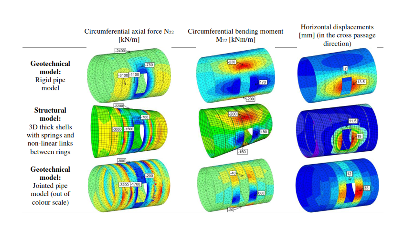
Figure 2: Structural model calibration based on upper and lower boundaries defined by the geotechnical models results. Source: Castellvi et al. 2023.
Both the special segments design and the innovative design methodology were successfully applied in many challenging conditions in this project, such as in large zenithal ventilation connections up to 28 m2 (Hoerrle et al. 2024) or in a large lateral cavern connection (Torelló et al. 2025). Even though, its application is especially relevant at 20 cross passages where ground freezing was employed for soil stabilization, introducing significant frost-induced pressures on tunnel linings.
To evaluate the critical frost pressures during freezing, a combination of laboratory tests, numerical simulations, and field monitoring was used. The details can be encountered at Torelló et al. 2025.
The monitoring data confirmed the high level of accuracy of the finite element modelisations, validating the modelling assumptions. The model results were consistent with the observed displacements, even in the freezing case, where the maximum recorded displacement (37mm in the special segments at cross passage 31), remaining within design limits.
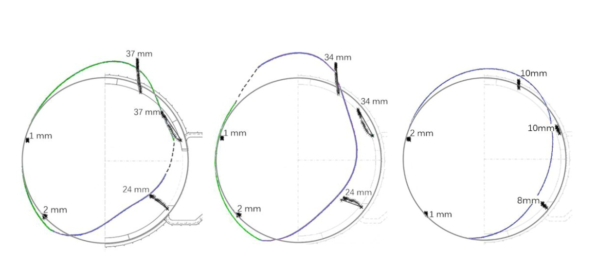
Figure 3: Monitored displacements in CP31 after freezing (in black) and tunnel deformed profile after geotechnical models. The deformed profile is the envelope of the rigid pipe model results (green line) and the jointed pipe model results (purple line).
Opening ring (left), adjacent ring to the opening (middle), third ring from the opening (right). Source: Torelló et al. 2025.
Conclusion
The presented methodology using PLAXIS 3D was a key point for a robust and accurate segment design in complex connection conditions. The methodology provided accurate predictions, optimised structural designs, and enhanced safety during construction. These real-life cases serve as a valuable reference for future tunnelling projects under complex loading conditions, emphasizing the power of innovative modelling in overcoming underground engineering challenges.
Acknowledgments
The authors would like to express their gratitude to the Züblin team, who led the design of these special segments.
This success story is published with the permission of HS2 Ltd. The authors would like to acknowledge Skanska-Costain-STRABAG Joint Venture (SCS) for their permission to publish the information shown in this success story.
Sources
This success story focuses on the methodology used to simulate the joints in tunnel connections. It is based primarily on extracts from two papers, which can be accessed here:
Torelló et al. 2020: https://learninglegacy.hs2.org.uk/document/special-segment-design-for-cross-passages-and-shaft-passages/
Castellvi et al. 2023: https://www.issmge.org/uploads/publications/51/119/NUMGE2023-202.pdf
Torelló et al. 2025: https://www.taylorfrancis.com/reader/download/806b4474-408a-498b-93aa-39bc375aebed/chapter/pdf?context=ubx
Additionally, the following papers can be referred for further information:
Hoerrle, D.; Acosta, F.; Neher, H. & Torelló, X. 2024. High Speed 2: Innovative dauerhafte Querschlagabfangung mit Tübbingen. Tunnelbau 2024: 110-149. Ernst & Sohn.