Preserve critical insights and validate decisions faster

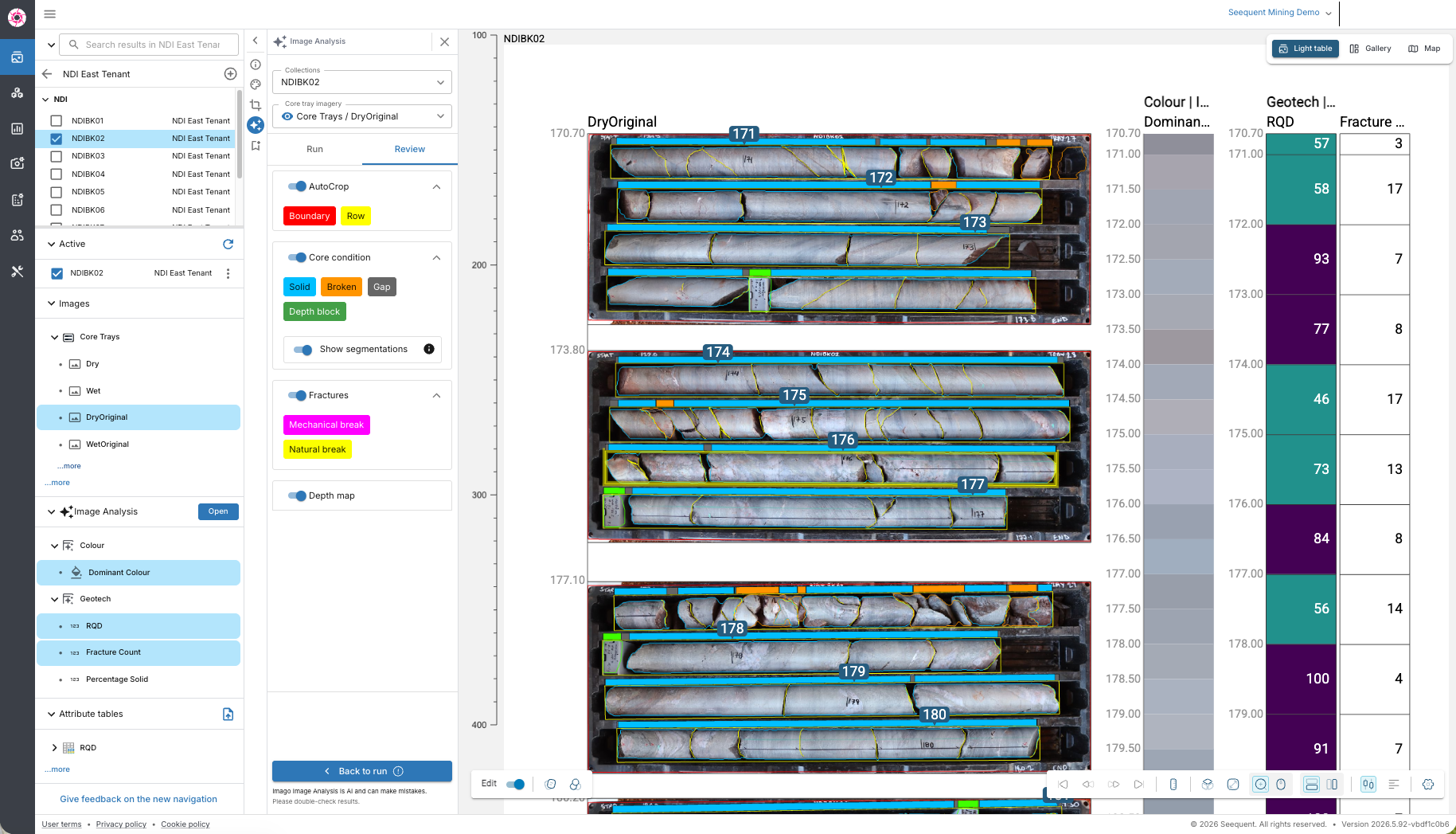
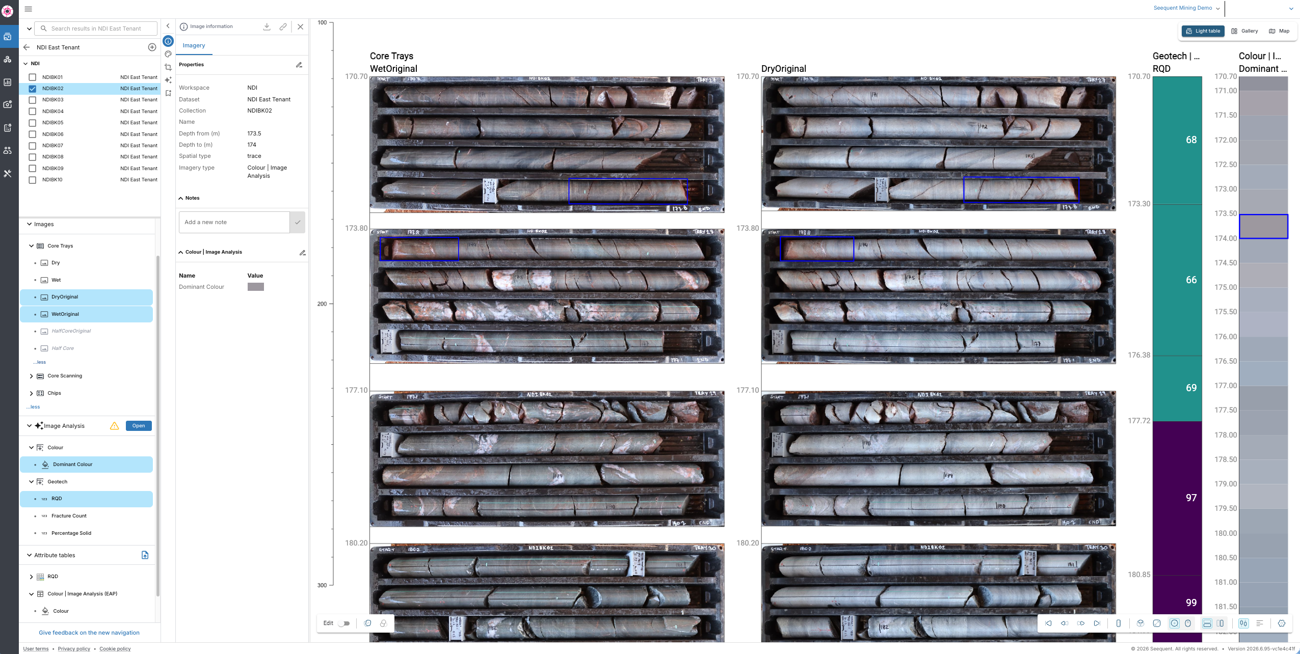
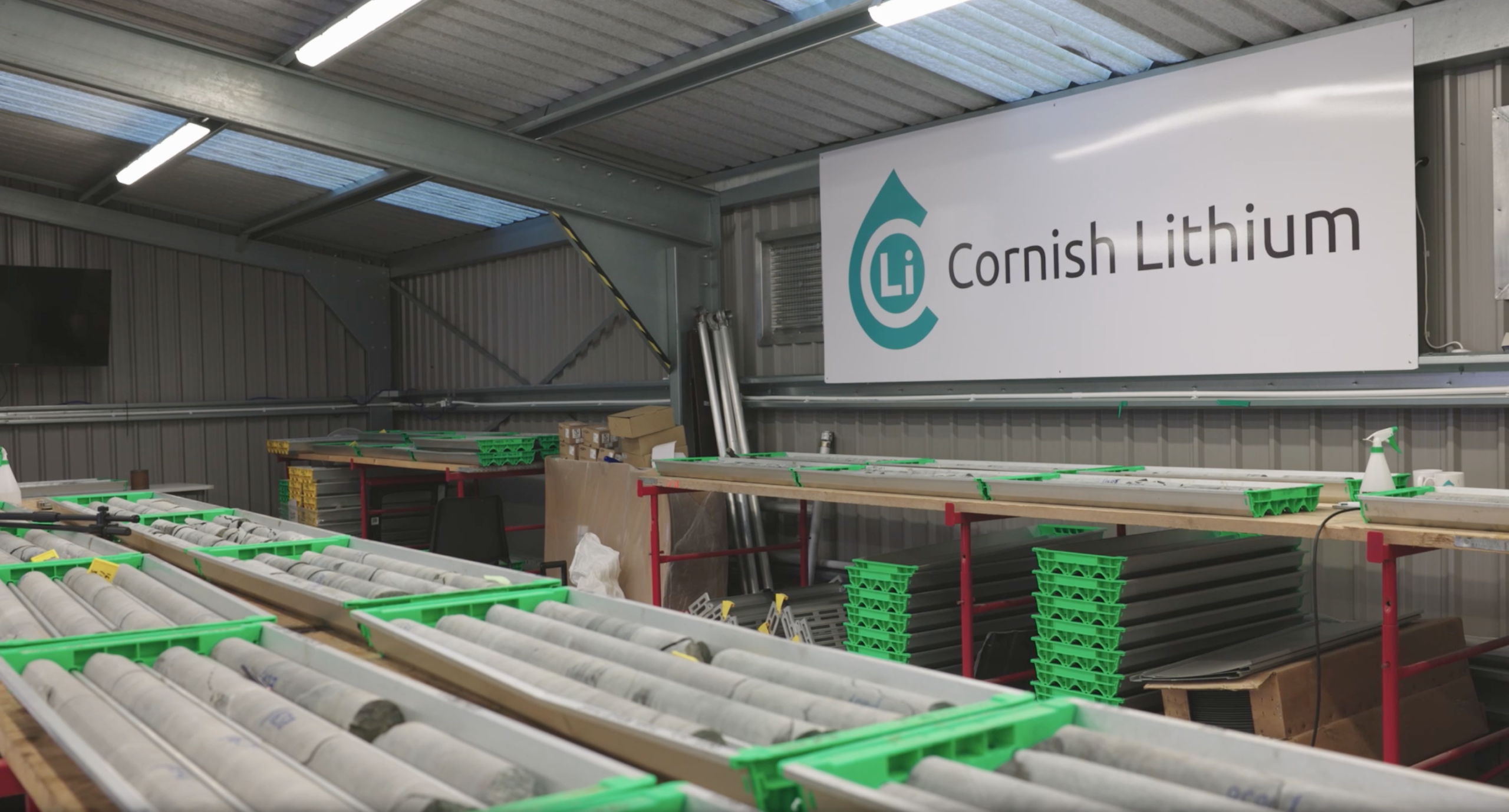
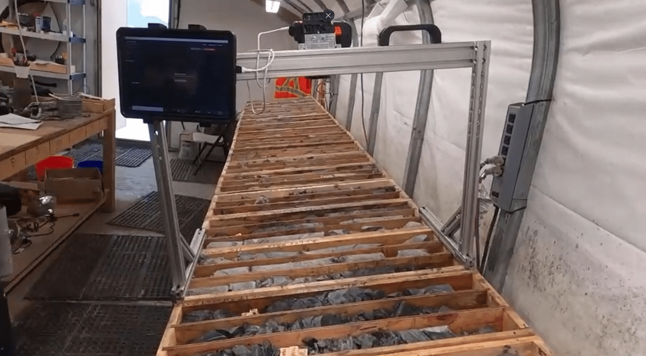
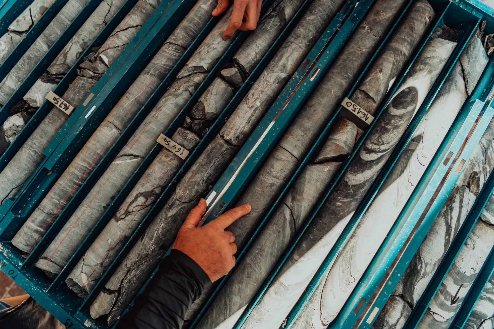
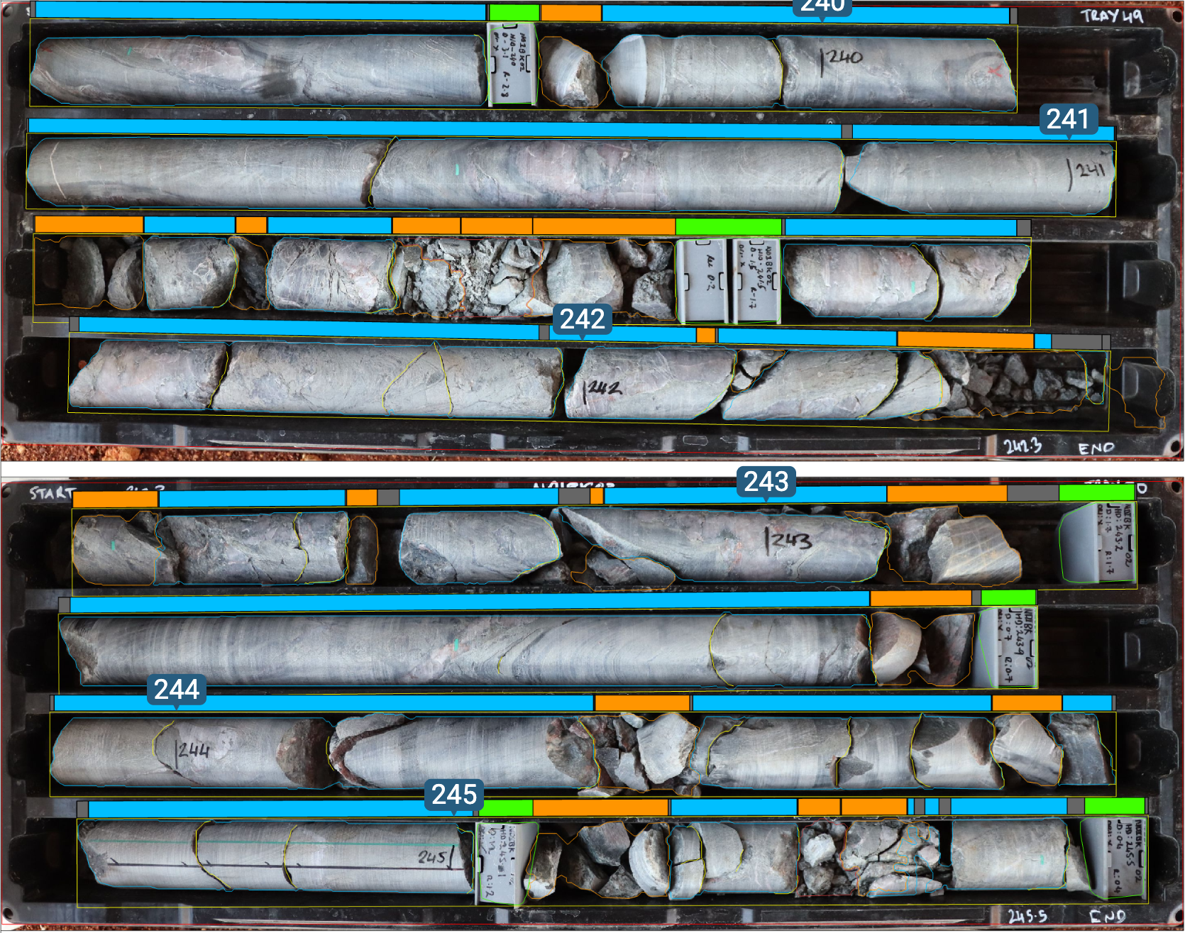
Streamline capturing and managing core imagery. Imago automatically crops, catalogues, and syncs after capturing images in the core shed. This data can be easily accessed or integrated with modelling tools such as Leapfrog to instantly validate decisions by placing imagery alongside data and models.