


Introduction
QUAKE/W is designed and implemented primarily for analyzing the effects of earthquakes on earth structures. The same implementation can also be used to investigate the effect of a sudden impact on the structure, such as controlled blasting in an open pit mine.
In a finite element stress-strain formulation, the activating forces can come as: (1) a body load, like an earthquake, (2) a specified nodal boundary force, or (3) specified nodal displacements. Velocities and accelerations cannot be applied as boundary conditions; at least not directly. Acceleration or velocity variations with time can, however, be integrated and applied as displacements with time at any particular location.
This example illustrates how this can be done. A velocity versus time record for an imaginary blast at the foot of a slope is converted into a displacement versus time function, and then applied as a boundary condition.
Numerical Simulation
Figure 1 shows the configuration of the problem. The downward arrows at the foot of the slope indicate the location of the dynamic boundary condition. Simple linear-elastic soil (rock) properties are used for this illustrative example. The Linear Elastic material model has been used with the total unit weight, Poisson’s ratio, Damping ratio and Gmax defined as 20 kN/m3, 0.334, 0.1 and 1,000,000kPa, respectively.
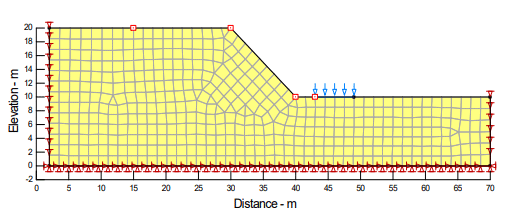
Figure 1. Problem configuration – arrows show location of blast.
As with all QUAKE/W analyses, it is always necessary to first establish the in situ stress conditions. This can be done with the Initial Static analysis option. Fundamentally, this involves a simple gravity turn-on analysis; that is, the gravity is turned on after the model has been set up. The gravity effect is modeled by applying the self-weight of each element as a boundary condition. The left and right boundary conditions are fixed in the x-direction for this in situ analysis.
The blast is simulated using an Equivalent Linear Dynamic analysis. The left and right boundaries are fixed in the y-direction with the bottom boundary fixed in both the x- and y-directions. The effect of the blast is specified by the velocity versus time function under the Force/Displacement boundary condition (Figure 2).
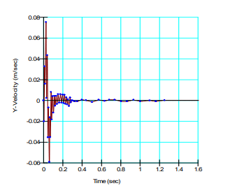
Figure 2. Velocity versus time function.
To capture the sudden change in displacement and the resulting reverberations, it is necessary to use very small time integration steps. This example uses time steps equal to 0.001 (1/1000th) seconds. A slope stability analysis is also simulated to determine the factor of safety of the slope as a result of the blast.
Results and Discussion
QUAKE/W integrates the area under the velocity versus time curve in the boundary condition to obtain the displacement versus time function (Figure 3). As indicated by the displacement function, the blast causes a sudden uplift in the ground surface.
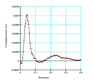
Figure 3. Resulting displacement versus time function from the velocity function.
There are many ways to view the impact of the blast. Only two graphs are shown here to illustrate what can be done. There is a History Point on the upland beyond the slope crest. The horizontal and vertical resulting velocities at this point are shown in Figure 4 and in Figure 5.
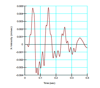
Figure 4. X-velocities on the upland.
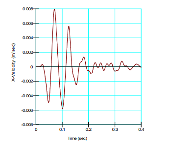
Figure 5. Y-velocities on the upland.
The Newmark deformation analysis type in SLOPE/W can be used to look at the effect that the blast has on the slope stability. The results from such an analysis are shown in Figure 6. The sudden uplift at the foot of the slope causes the safety factor to increase suddenly, and then oscillate more or less about the static factor of safety. There are, however, some indications that the factor of safety does fall below the initial static value momentarily.
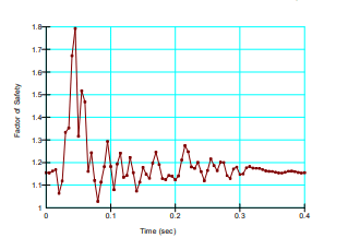
Figure 6. Factors of safety with time due to the blast.
The factor of safety at no time drops below 1.0, and so the Newmark analysis infers there will be no permanent deformation.
The input for an analysis like this could possibly be obtained from a monitoring seismograph at a site, which can record velocities and or accelerations in multiple directions.
Summary and Conclusions
The data used in this example is not all that realistic, but it is sufficient to demonstrate what can be done with QUAKE/W in conjunction with SLOPE/W to investigate the effects of a sudden impact on an earth structure.